Wednesday, October 19, 2005

mi theremin and the blinking lights

Oscar, the Theremin Hispano webmaster, has noticed my site and is exposing his Spanish-speaking readers to my theremin-building adventure here. His theremin blog, “Mi Theremin,” is located here.

In other news, check out what I found while digging through my mom’s old stuff at grandma’s house:
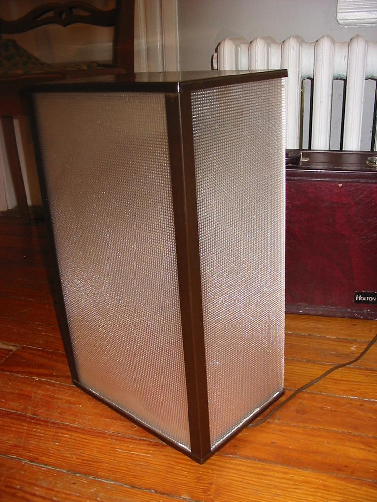
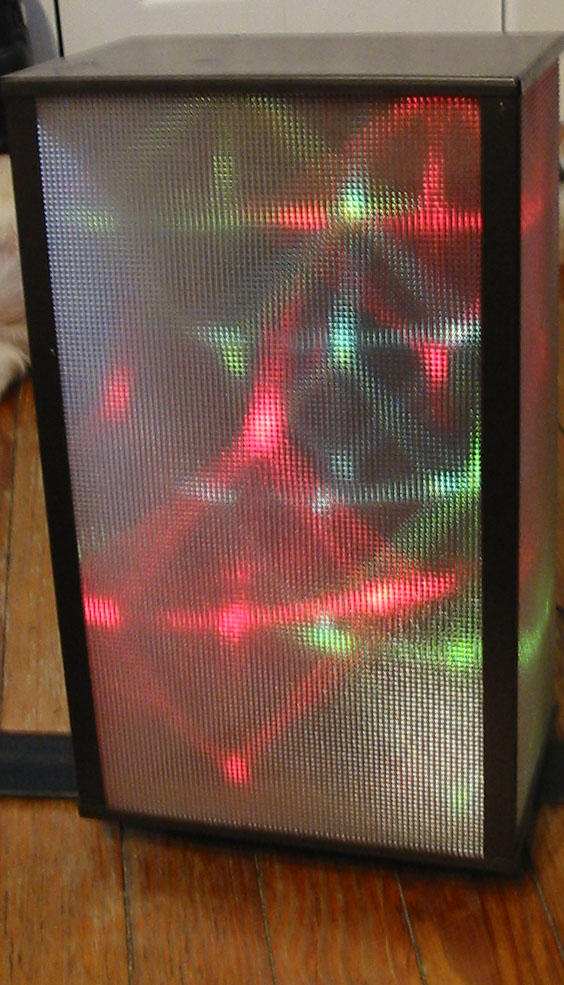
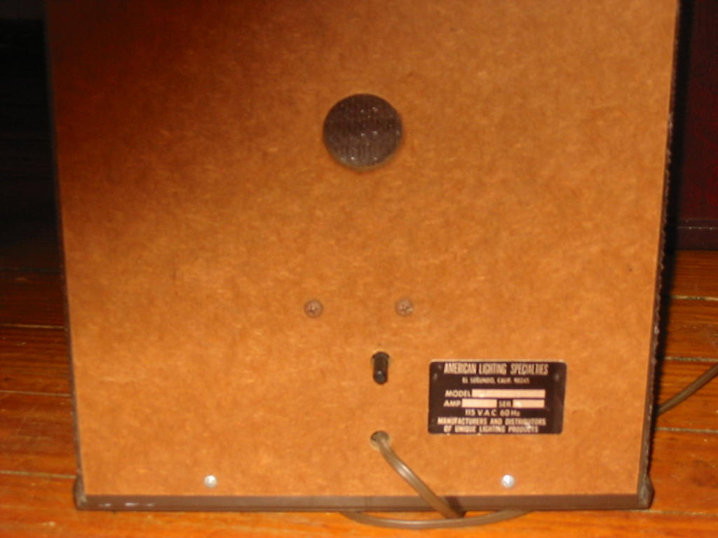
That’s right, really old sound-responsive light box. Made in California God-knows how long ago of fairly cheap material, this is a good sized box with more than enough room for some Theremin circuitry.
I think the sound-responsive lights could add some new dimension to the visual spectacle that is the operation of the theremin.

Aside - Speaking of visual spectacle, anyone see Gabby La La recently? She is touring with Les Claypool, saw her at Toad's Place in New Haven, CT two nights ago. She busted out with the theremin, and had a mean Theremin duel with Les (on bass obviously). Her music is very fun, I guess she is primarily a sitar player, and she excelled with the all-star musicians she was with. Her site is here.

Theremin PCB - see you on the component side

When we left off last time, I had just put the finishing touches on the copper-trace side of my theremin circuit board. This included sanding copper off of the other side of the PCB; I removed the copper - but despite my best buffing efforts I could not return the board to its smooth state. Read on to find out how this turns out.
Materials needed for creation of the flip-side of theremin PCB:
  • copper-trace side of board from previous steps completed
  • image of component side of PCB printed recently on glossy paper from laser printer (check Chris's RS Theremin site for more info)
  • iron
  • paper
So I followed basically the same steps as I did for silkscreening the other side. I taped the pattern face down on the copper-less side of the circuit board, placed another piece of paper on top of the pattern, and ironed away.
I ironed alot, because I noticed that some areas of the paper were not showing any toner. The paper came right off after I stopped, and it looked really bad. So I tried again with a new printout on the same board, and this is the best I could get.If you look close, you will notice that all the areas that the silkscreen image did not transfer are the scuffed areas where I sanded the remaining copper off.
I decided that putting all the components on this board might end up being a waste of components because in some areas on the other side the copper traces were far less than perfect. I will make a new board as soon as possible, stay tuned for more theremin updates shortly!
I think I just might have found the perfect enclosure to put my first theremin in ...

Tuesday, October 18, 2005

Creation of PCB (part 2)

This post is a continuation of the creation of the bottom side of my theremin circuit board. With that said, let's begin! [see materials from previous post]

After I silkscreened the board, the magic began to happen.
I dropped circuit board with the paper adhesed into a large bowl with enough water to submerse the board, and let it sit for about 10 minutes as the paper crumbled away.


Upon extraction from the bowl, and rubbing the remainder of the paper off the PCB, you should get a board that looks like this:

The brighter white segments of the traces are where I used a white-out pen (after soaking the board) to protect areas that did not transfer properly. For the etching process, I used the same bowl. I emptied out the water and poured in half a bottle of Radioshack ferric chloride Etchant. The object here was to ensure that the copper board had ample room above and below to sift the copper away.

After rocking the bowl slightly from side to side for about 30 - 40 minutes, I disposed of the etchant solution in the toilet and rinsed my board with tap water. The board looked okay, but the back of it had some copper remaining. I re-soaked it in etchant, using the other half of the bottle, and still could not remove all the copper from the non-silkscreened side.

I used these neat little tools with the Dremel to remove the white residue from the protected copper traces, but a fingernail would suffice.

The hole-drilling occurs now. Somehow a friend with much more skill in PCB construction than I shows up and volunteers his skill to drill all the holes with a 1/16" drill bit. I would recommend a smaller bit if at all possible!

After being unsuccessful twice at removing all the copper from the other side of the circuit board, I decided that using the Dremel to sand off the copper would be the most prudent thing to do at this juncture.

Will this be a good idea? Find out in the follow up post tomorrow, when I show my success at silkscreening the board's component side.

Monday, October 17, 2005

PCB Creation 101

Materials used for this step of circuit board creation:
  • PC board from Radioshack
  • PDF image from Chris's RS Theremin Page
  • glossy photo inkjet paper
  • Laser Printer
  • Etchant solution (ferric chloride)
  • large plastic bowl
  • 1/16" drill bit
  • Dremel coarse cutting bit
  • White-Out pen
  • Iron
The first step in this part of the adventure is to trim the board to size. As you can see, the stock dimensions of the copper board from RS are slightly larger than necessary. Here is where I utilize the ever-helpful Dremel... carefully cut the board to correct dimension...


And generate this fine looking board (remember to clean, windex works for me!):
Next, I printed the diagram to be silkscreened for the copper traces on the non-component side of the board. This is the bottom half of the PDF printout, with all the curvy lines. (By the way, Chris is willing to send this PDF file to anyone that requests it via his web page). I tried printing the image many times on our HP Laserjet (which is a bottom feeding laser printer) to no avail. Finally, as a last resort I decided to try my sometimes-working Samsung top-loading laser, which fed the paper fine. Note - using a laser printer is important, because it is the toner that will transfer onto the copper board and protect the traces and pads. After printing off the sheet, I cut around the diagram, leaving about a half inch of excess paper to tape to the board. Then, the diagram gets taped face down on the copper board, with another sheet of normal printer paper on top (over the photo paper). Now for the ironing:
Recommended iron settings: Cotton setting, lay on top of the top piece of paper for 1 min to preheat, then thoroughly iron using edges of iron.

OK, due to server congestion or limits on blog post sizes, I am having difficulty adding more pictures to this post, so I will continue with Part 2, when "PCB creation" returns tomorrow!

Friday, October 14, 2005

Thanks for the interest!

The two sites that I supported in my blog have both written me up on their respective pages. My blog appeared on the Theremin World news feed today, and Chris's RS Theremin website also added a link to my adventure in Theremin building.
Thanks for the support, and I hope that this blog can continue to provoke interest in people both new (like me) and long-standing in the theremin community. Remember that I encourage any and all comments; the construction of this instrument is as much of a learning experience for me as anyone else.

Thursday, October 13, 2005

And then there were Two (sound coils)

... and they were happy lying next to each other.
But first, I started out by lying this tube next to the one I completed the night before so I could attach the tape and begin winding in the exact same spot (see previous post for Materials Used). Creating the sound coils identically is my goal here.

The finished product is here. The second coil does not include the loop at wind number 50, otherwise it is identical. The creation of the sound coils done, look forward to the theremin brains before the weekend is out!

In the beginning there is carpal tunnel (Winding the first sound coil)

The purpose of this blog is to account for the effort of a first time theremin-builder, and provoke encouraging advice on possible improvements or other applications of the equipment used and built . Mistakes and successes will be given equal coverage in an attempt to help the reader learn as much as possible about the thrilling prospect of creating a Theremin!
For background on Theremins please see: Theremin World.

After collecting all the supplies necessary to build a working theremin according to Make the Theremin Circuit using only Radio Shack, I began building the first sound coil.
The supplies in this picture that I used for this step were

  • 1" PVC cut to 3" length
  • Radioshack red #30 wire
  • double-sided tape 2" long
  • the desire last night to start somewhere that did not require any specific skill
Having gathered all of this in one place, finding myself with some free time and a functioning digital camera, I struck forth on this bold undertaking: beginning to create a sound coil.


First attempt = lousy. There is no way I was going to fit 100 winds of cable with spacing like this. I decided to start over after wind number 18.


After wind 25 I make a loop for future circuit board/antenna connection.


I continue winding, making loops in turn 25, 50, and 75. Interesting to think of this plastic tube and wire as being responsible for shaping the sound in a musical instrument.


After winding wire for an hour or so my hand cried out for a break, and I decided that this was definetly a job for a robot. Mass-producing theremins such as these would definetly cause some form of carpal tunnel anxiety as a result of this cable winding process. Update on the slightly different process of winding coil number 2 coming tomorrow!